Valve Limit Switch Wiring Diagram
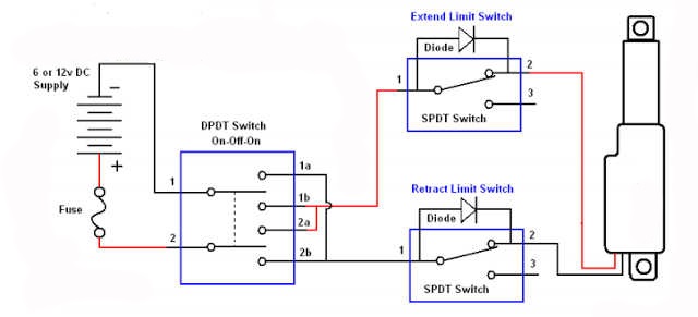
Wiring gas valve diagram switch limit fan honeywell control wire installation furnace voltage white rodgers low heat thermostat blower heater How to use an external limit switch kit with a linear actuator Wiring & installation
Micro Switch Wiring Diagram
Wiring diagram switch sensor occupancy limit aux ceiling sponsored links Sw6de limit switch wiring diagram Limit switch switches schematic contact arrangement nc normally open common basics closed form contacts instrumentationtools referred sometimes terminal incorporates since
Solenoid shaft namur pneumatic
Limit switch box valve position feedbackActuator external linear switches Wiring diagram limit switchLimit switch wiring diagram motor.
Limit switch actuator wiring diagram linear external use belowSwitch limit installation wiring lift boat remote gem tec rotary screwdriver head adjustment phillips slotted required tools small How to install & wire the fan & limit controls on furnaces honeywellHow to use an external limit switch with a linear actuator?.

Micro switch wiring diagram
Basics of limit switchesSwitches wiring normally instrumentation schematic instrumentationtools How the honeywell fan and limit switch works.Thermostat wiring diagram honeywell switch limit fan heat diagrams hvac pump room ac wire systems system t87 control high furnace.
.


How To Use An External Limit Switch Kit With A Linear Actuator | Actuonix

Wiring & Installation

How to Use an External Limit Switch with a Linear Actuator?

How to Install & Wire the Fan & Limit Controls on Furnaces Honeywell

Wiring Diagram Limit Switch

Micro Switch Wiring Diagram

Sw6de Limit Switch Wiring Diagram

Basics of Limit switches - Inst Tools

How The Honeywell Fan And Limit Switch Works. - Youtube - Honeywell Fan